Jarrow
EM Scale,
Lead – Trevor Smith
Dimensions – 22′ x 10′
Control Method – DCC
Why a layout focussed on Jarrow?
Jarrow was chosen because in 1983 it had a Tyne and Wear Metro line alongside a main line and a small yard serving a nearby steel works.
The Metro line from Pelaw to South Shields is single track. There is a passing loop at Jarrow to allow an intensive service of Metro trains. This provides the opportunity to model two platforms and to have one train wait for another to approach from the opposite direction. Add the pointwork and accurate signals and this will provide interesting operation for viewers. The main line served the Jarrow oil Terminal and the Simonside Wagon Works. The “Jarrow Tanks” is an iconic modern freight train and would make a good model.
The sidings originally served a small goods depot at the station and provided an interchange with the docks on the south bank of the River Tyne. In 1983 the yard served a small British Steel works.
Trains on the layout would include;
- Tyne and Wear Metro cars,
- Engineers trains on the Metro line,
- dedicated trip workings between Tyne Yard and Jarrow Sidings with wagons to and from Simonside,
- Jarrow Tanks,
- Steel carrying wagons for the British Steel Works,
- Roundtrees Trip workings between Fawdon and Tyne Yard diverting to Jarrow to pick up and drop off wagons for Simonside,
We want to promote the ethos of the Blyth and Tyne Model Railway Society and develop our own skills. We had to ask ourselves a number of questions and then attempt to find solutions and answers as the layout is built.
- What makes a believable scenario?
- What modelling elements do we need to bring together?
- What look and feel do we want to capture?
- How do we model the train formations used?
- How do we model the railway infrastructure?
- How do we model the non-railway infrastructure?
- What should the pattern of train service look like?
- How do we ensure the accuracy of locos and stock?
- How accurate should our weathering be?
- How do we build the stock to ensure scale speed operation?
- How accurate can our track plan and signalling be?
- How do we make sure he running of trains is linked to the industries served in the geographical location of the layout?
In the 1950s and 60s railroad modelling became very popular in the USA. John Armstrong became a well renowned modeller with a special interest in layout planning. He adopted the phrase “givens and druthers” to help modellers to determine the framework of their layout before they started any planning.
Givens are elements that must be included in a layout
Druthers are the wish list of elements that might be included in a layout
Givens:
The layout must be of an exhibition standard.
The layout must be portable, board size no bigger than 4′ x 2′ and the boards must be light.
Name Jarrow
Period Summer 1983
Location Jarrow, on the Metro line along the South Bank of the River Tyne, between Gateshead and South Shields.
Size 22′ x 10′, baseboard height 44″.
Planning Track plan to be drawn using Templot to ensure prototypical track alignment through pointwork.
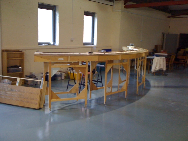
Baseboards Lightweight, capable of being lifted by two people, manufactured from laser cut 6mm plywood with a foam surface. Permanent 2” x 1” timber legs hinged and folded inside each baseboard. Each baseboard self-contained with hand holes. Boards aligned with EM Gauge Society alignment dowels. Baseboards to have integral back-scene and lighting unit. Baseboards to be stackable within a wheeled cabinet. Each baseboard to be self-contained with stationary decoders controlling pointwork on its own board. Baseboard electrical connections to be plugs on the inside face of the baseboards so no crawling underneath the layout is necessary.
Operators
- One for the Metro line
- Two for the freight operations
- One fiddle yard operator
Operations The layout to have accurate signalling and all trains to be operated at scale speed and in accordance with signals. Spratt and Winkle couplings to be used so that all operations are hands free.
Gauge EM Gauge
Track Handmade using
- Exactorail EM Gauge concrete sleeper bases
- Code 83 nickel silver rail
- Copper clad sleepers
- SMP bullhead rail flexitrack
- Tortoise point motors
Maximum grade 3%
minimum radius 36”
Roadbed Cork. Woodlands Scenics buff fine ballast held in place with Johnson’s Klear
Rolling Stock All rolling stock relevant to the period and evidenced from photographic research. Remote uncoupling using Spratt and Winkle couplings. All vehicles appropriately weathered. Road vehicles appropriate to period and location.
Control Gaugemaster Prodigy with circuit breakers to create a power bus for trains and a power bus for points and signals. Handheld controllers with multiple plug-in sockets. Automated turnout control with Tortoise Turnout Motors activated with Lenz LS100 stationary decoders. Prototypical signals activated by Lenz LS100 stationary decoders. Working station and yard lights.
Scenery Scratch built station and derelict goods shed. Accurate bridges and roads. Appropriate signage and back-drop.
Fascia and valance To be painted black to enhance layout.